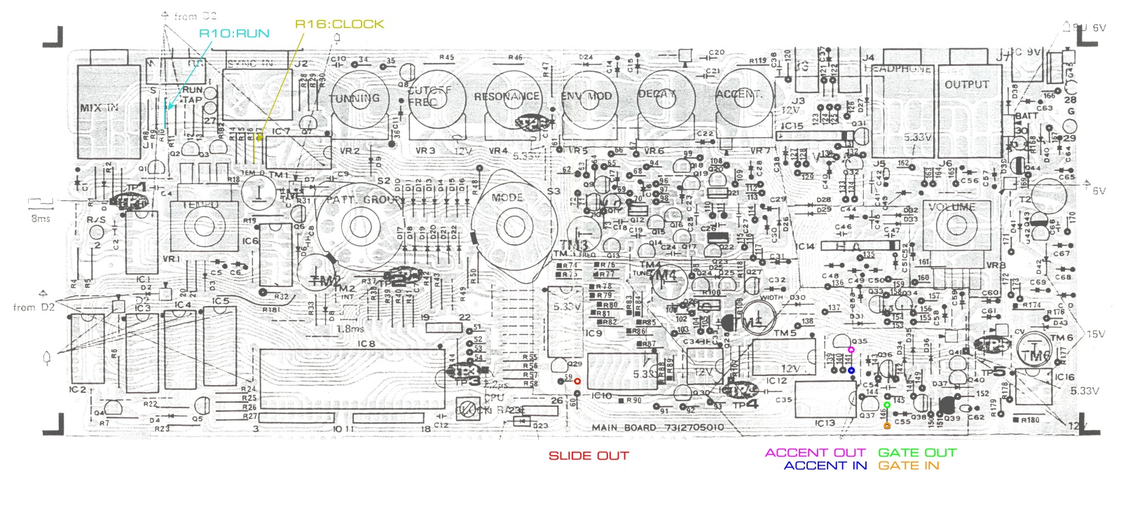
For clarity, here is an image showing the connection points for the MIDIBass wires (except Filter CV, which goes to the rear of the board) superimposed on the component layout of the 303 from the service manual.
Click on the image for a larger version:
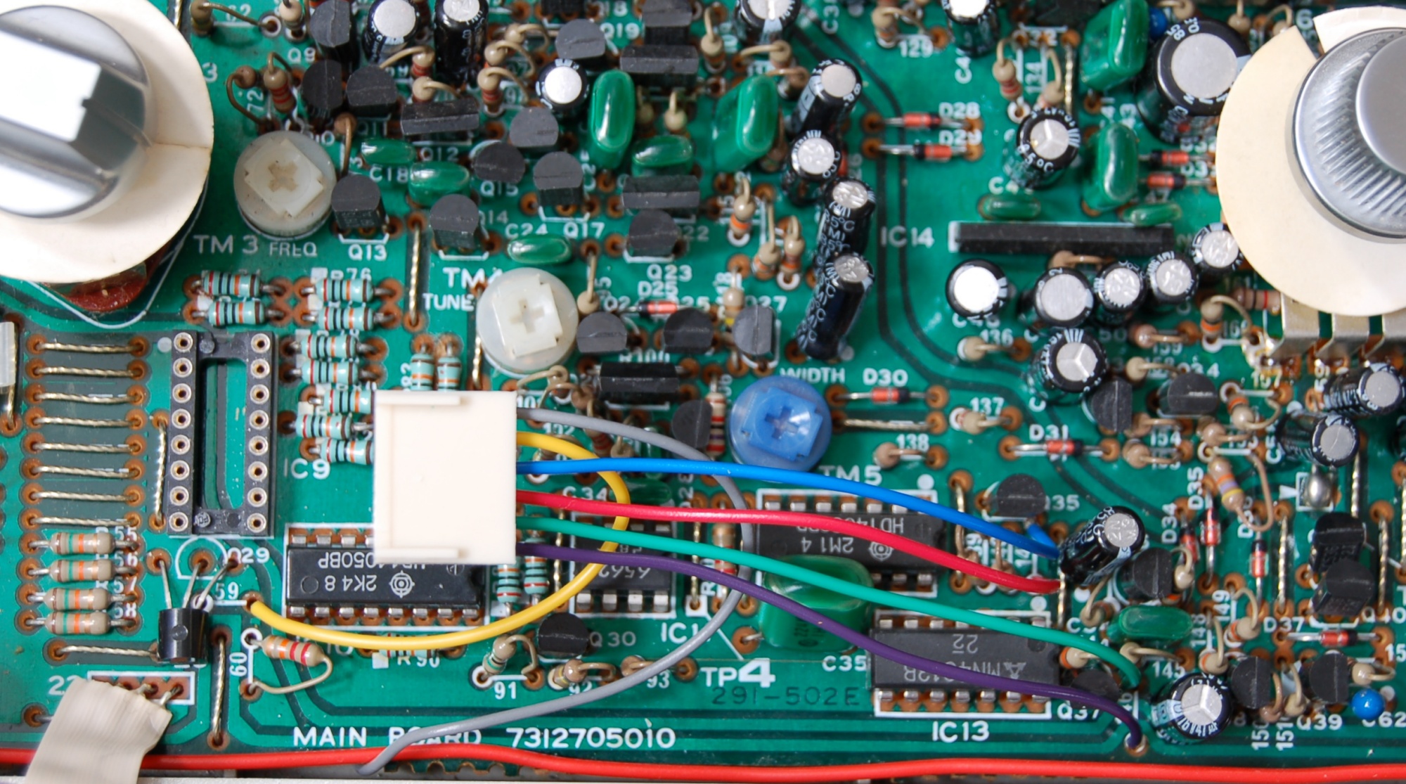
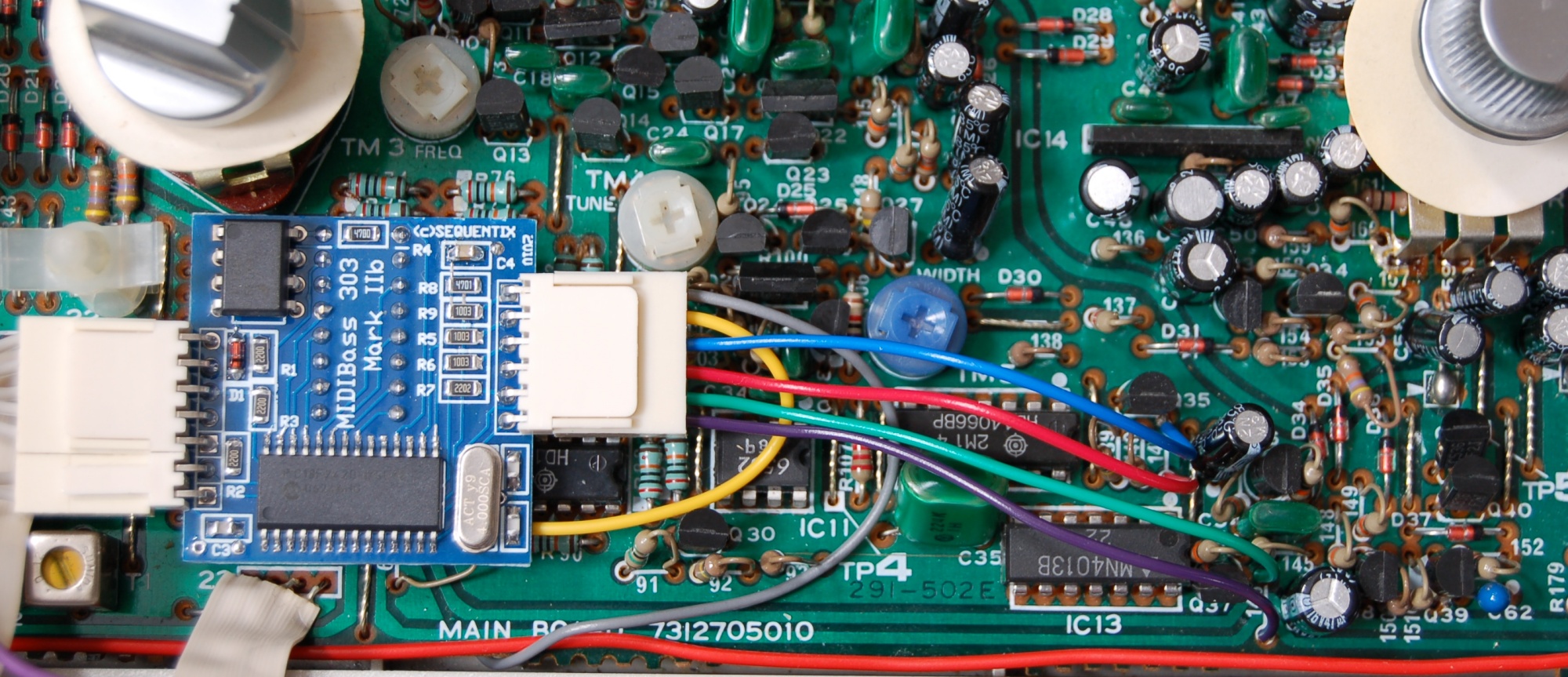
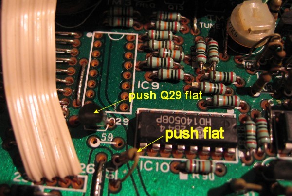
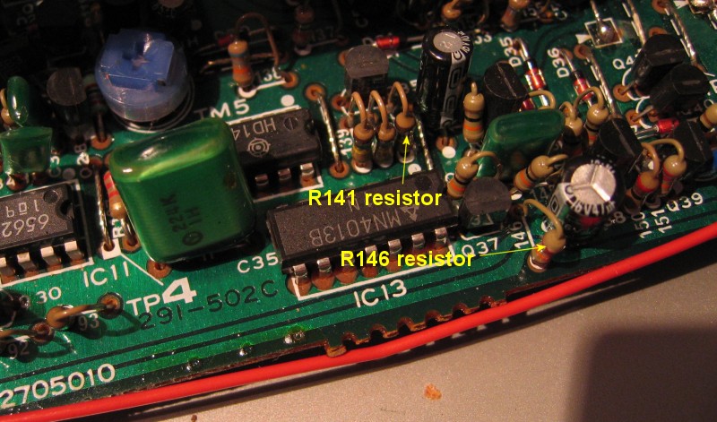
Finally here are images of the 6 pin wiring connector in place, with different colour wires to make the connections obvious.
First without the MIDIBass fitted, so you can see the SLIDE connection, then with the board in place.
Note the 303 switchboard is pulled forward here, just to let you see properly. The filter CV connection to the rear of the board is shown in a following page.
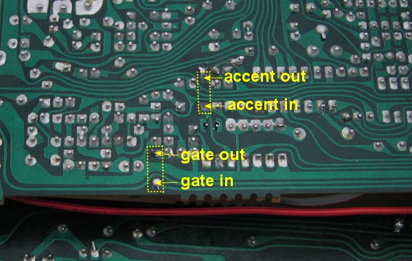
N.B. The Mark II board has been revised to a IIb version.
The only difference for installation is that the ACCENT IN and OUT pins are swapped on the board so the wires dont cross.
The original Mark II boards are BLACK, the Mark IIb & IIe boards are BLUE.
This image shows the Mark IIb board.
Click here for the original Mark II board images.
Click on the images for higher-res images: