MIDIBass 303 Installation
Component Removal
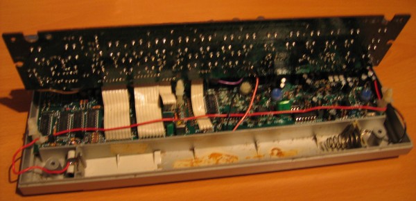
Once the switchboard is clear, you will see the components that will be removed to fit the MB303 board.
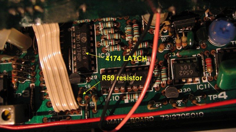
Here are the 4174 latch, and resistor R59 (which carries the SLIDE signal):
And here are the pads underneath you must de-solder to remove the IC and resistor. Once the IC is removed, the 16 pin DIL socket should be soldered in its place.
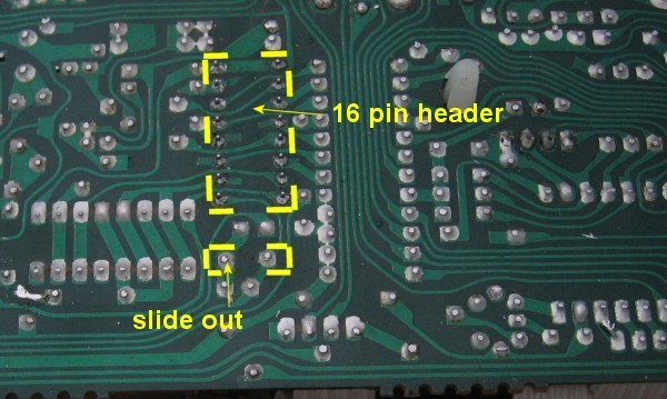
In place of resistor R59, the 'SLIDE OUT' wire from the '303 CPU' 5 pin connector needs to be fitted to the pad shown above.
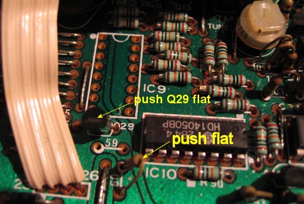
To allow clearance for the MIDIBass board, transistor Q29 and resistor R60 must be gently pressed flat to the PCB - Q29 can only be flattened once R59 is out of the way:
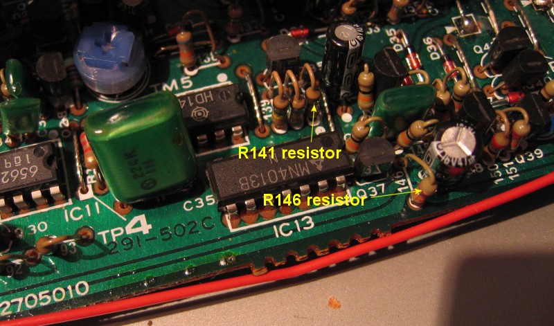
Here are resistors R146 (carrying the GATE signal) and R141 (ACCENT):
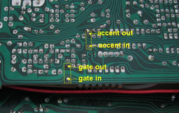
And here are the corresponding pads to de-solder for removal of these resistors, along with the wires to attach from the '303 CPU' connector:
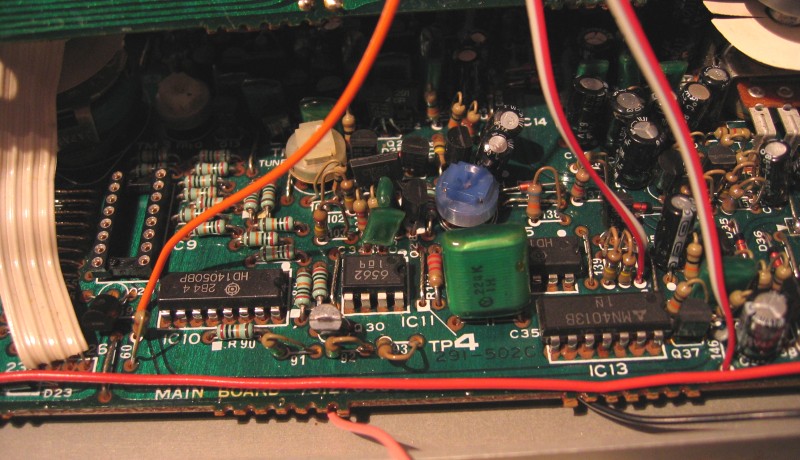
Once IC9, R59, R141 and R146 have been removed and replaced with the socket and 5 wires, your 303 board should look like this:
For clarity, here is an image showing the connection points for the MIDIBass wires superimposed on the component layout of the 303 from the service manual.
next page >>
MB303 home