Main board
The main board is obviously the most complex of the P3 boards, but assembly is not too difficult if you follow the usual process - start with the smallest components, i.e. resistors and diodes, then work up. I use a PCB soldering jig with a foam-lined lid to hold all components tightly in place while soldering. If you build a lot of kits, I'd highly recommend investing in one.
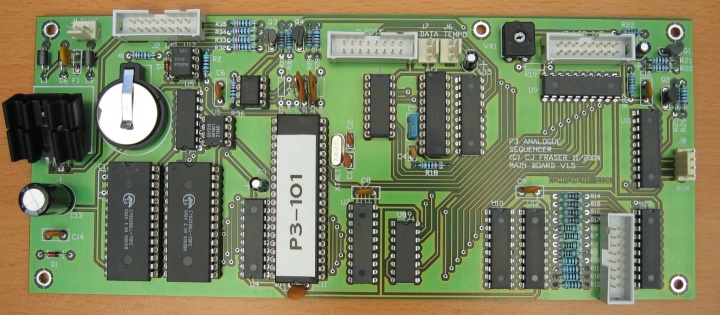
For reference, here is a fully populated mainboard (click for a larger image):
There are a few component options on the mainboard, depending on whether you want the SYNC output on the I/O board to carry DIN sync or clock-only MIDI output, and whether you want to use a PLED or LCD display module.
A backlit LCD display module requires R19 to be fitted. If you use the standard PLED module, this resistor is not required.
For clock-only MIDI SYNC output, FIT R36 and IC19, and OMIT components R23, R24, D2, D3, D4 and D5.
IC19 is a PIC 12F629 (or 12C508) written with my DIN to MIDI sync conversion code and available as a kit option.
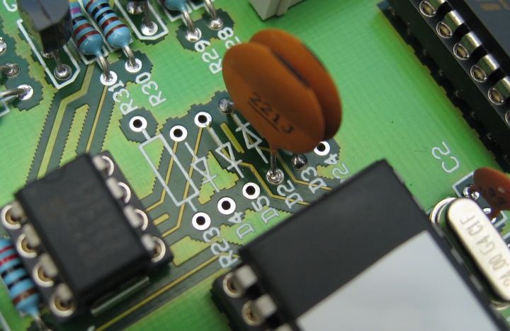
I have found the input pins of these chips have a problem with false triggering when used in the P3 mainboard as is, but this is cured by the addition of a little capacitance - 220pF ceramic caps should be fitted in place of D2 and D3, as shown here:
For the standard DIN SYNC output, FIT R23, R24, D2 and D3, and OMIT R36 and IC19.
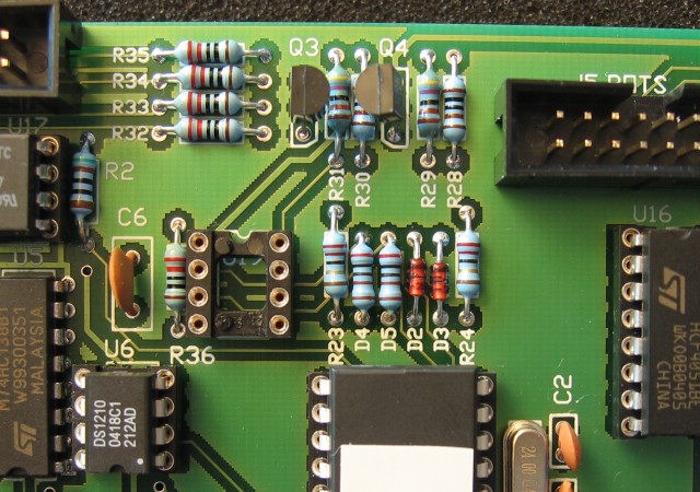
The newer P3 CPU outputs seem to have less drive capability than the previous CPU, and this can limit the number of DIN sync devices which can be connected in parallel to the DIN SYNC output. To improve the drive capability, I have replaced diodes D4 and D5 with two 2k pull-up resistors, as shown here:
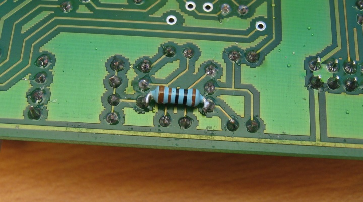
When the P3 I/O board is fitted with three-pin RFI filters, the extra capacitance on the MIDI data lines can slow the rise times of the MIDI signal enough the cause problems with some MIDI input stages. To remedy this, a 1k pull-up resistor can be added to the open-collector MIDI output stage on the mainboard.
This resistor should be soldered on the reverse side of the board, between the 5v supply and the collector of transistor Q3, as shown here:
back