Input/Output board
The I/O board features six 5-pin DIN sockets: one for MIDI in, four parallel MIDI outs (which all carry the same signal), and a SYNC socket.
The complete board will look like this:
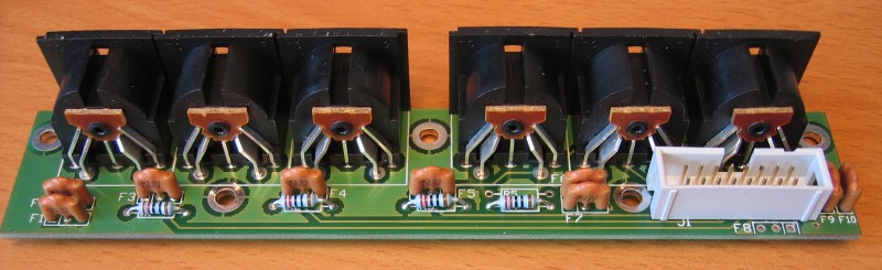
Note that in the picture above, resistor R5 and filter F8 are not fitted.
This is because the SYNC socket can be wired either for DIN sync, or with an additional PIC DIN to MIDI convertor chip fitted to the mainboard, can output clock-only MIDI - useful for syncing up external arpeggiators or drum machines without sending them unneccessary note data. The component differences are:
For DIN SYNC, FIT F9 & F10 and OMIT R5 & F8
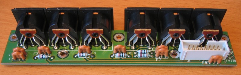
For MIDI SYNC, FIT R5 & F8, and OMIT F9 & F10
When configured for clock-only MIDI sync, the board should look like this:
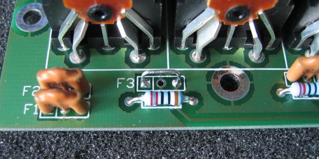
Production units are fitted with 3-pin RFI filters on all input and output lines, in order to safely exceed EU and FCC emission standards.
These filters are not strictly required if you are building P3 from a kit and not for commercial sale.
If you don't want to use them, wire links can be used in their place - the links should connect the outer two pads in each filter location, taking care not to short out against the centre connection, which is chassis ground:
back