Final Assembly
Note that this page assumes you are using a production case. For a DIY-constructed case, you'll need to work out how to assemble it yourself.
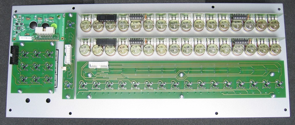
Once you have finished populating all the PCBs, they should be mounted to the front panel and lower case using the M3 screws supplied, except for the pot boards which are attached with nuts on the pot bushes. The PLED module must be fitted first as the function key board overlaps it slightly.
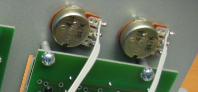
The DATA and TEMPO pots are mounted directly to the front panel, and are also held by their nuts. Each pot should have 200mm of 3-conductor connecting wire soldered directly to the pot pins, with a 3 pin plug on the opposite ends. Pin 1 of the plug goes to the clockwise end of the pot track, pin 2 to the wiper and pin 3 to the counter-clockwise end.
The main and I/O boards are fitted to the lower case. A short ribbon cable should be made to connect these boards - around 50mm of ribbon can be folded to give something to pull on when the cable needs to be removed:
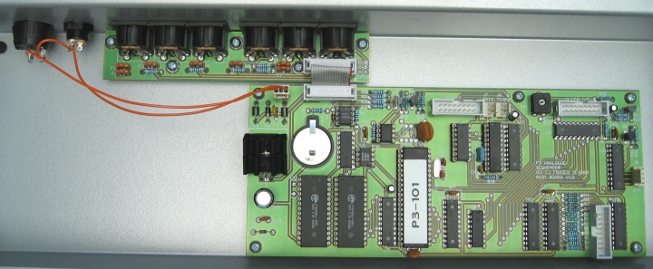
The power socket and switch are mounted directly to the lower case, and wired as shown:
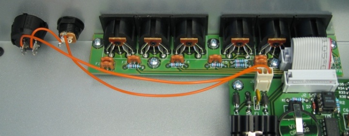
I use a 2.1mm connector for power input, wired for centre positive polarity. You can reverse the polarity to suit a different PSU if you wish. The switch can be wired to break either of the power supply connections to the main board - I tend to always wire it into the positive line.
Pin 1 of the power connector (nearest the left edge of the board) on the main board is ground (0 volts), pin 3 is the positive (or AC) supply.
To connect the front panel boards to the main board, you will need to put together a set of three ribbon cables, and one fly-lead, in addition to the leads already soldered directly to the DATA and TEMPO pots.
This image (click for full size) shows the lengths, and connector positions, for each of the pot, switch and PLED ribbon cables. Note that the red wire indicates the pin 1 connection, and should always line up with the arrow on the connectors. Pay careful attention to any connectors which are reversed on each of the cables.
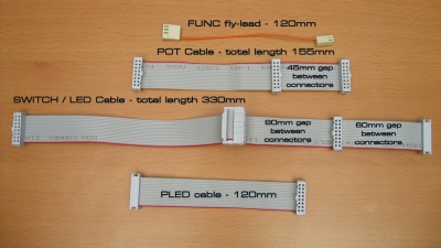
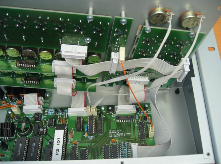
The cable lengths are kept to a minimum to prevent noise pickup or transmission. This makes it a little bit awkward to fit the cables to the main board and close the case unless you do it in the right way. Sit the lower case on a flat surface, then place the front panel on top so that the upper pot board sits against the back edge of the lower case, and the front panel is 'hinged' up at the front. From this position, all the cables can be attached, and the front panel then closed.
This picture shows the cables in position, with the front panel sitting at an angle further inside the case:
Once the cables are all connected, the case can be closed, and your P3 tested... good luck !
When you are happy it's working as expected, fit and gently tighten the M3 hex screws to fix the front panel.
back