
And Building your P3 Sequencer continues...
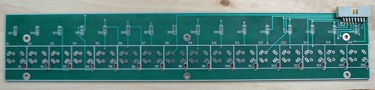
The Step Switch / LED Board
This board has 16 Tri-colour LEDs, 16 key switches, 16 diodes, and a 16 pin RIGHT ANGLED IDC connector. You wont be able to fit the cable to the board unless you use a right angled connector.
This photo shows the board after the first stage of assembly - fitting the non-light emitting diodes, and the IDC connector:
The process I use for fitting the LEDs to the correct height is the same as for the Function switch board. I put the LEDs loosely into their holes, making sure to observe the correct orientation, then fit the board to the panel, and feed the LEDs into the panel holes so they are all at an even height.
N.B.These Tri-colour LEDs have 2 anodes and a common cathode. The anode for the RED LED has a right-angle at the top of the component leg. The GREEN LED has a 45 degree angle at the top of the leg. The RED anode should go toward to top of the board, and the GREEN anode in the hole with the square around it on the component overlay.
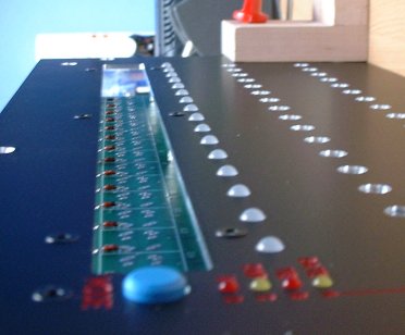
Here's the board with the LEDs just sitting in place - not soldered !
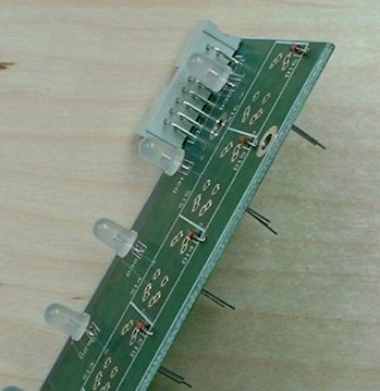
Then with the board fitted to the panel, and the LEDs fed into their holes:
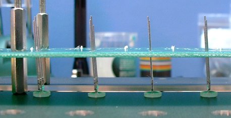
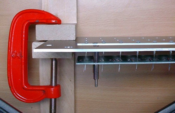
But I find they stick too far out the other side of the holes, so I hold the panel vertically using a couple of bits of wood and a G-clamp. Then I position the LEDs with just the right amount poking through, and solder them in from behind. I just solder the middle pin to begin with, so I can easily adjust them if they are not all quite at the same height. If you do clamp up your panel, be sure to use something soft so you dont mark the surface !
The end result should be a nice neat row of LEDs:
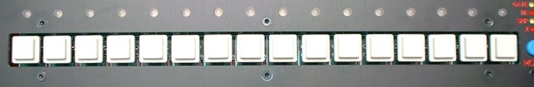
Final stage of the step board assembly is to fit the key switches. The Maplin type I use really need to have just one pin soldered first, then I check them from the front to make sure they are dead square with the panel and each other. I do this with the key caps already fitted, as there seems to be a bit of variation in the alignment of the plungers. You'll see what I mean when you put one together...
Once they are square, I solder the second pin. Make sure the bottom of the switches are flush against the surface of the PCB too.
The end result should be a neat row of step switches, as shown:
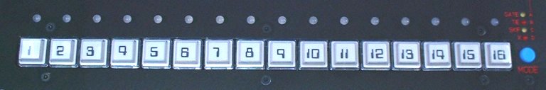
Then I fit the clear cap covers and labels once I've printed a set out and cut them up. You'll find a PDF of the labels, with lines to show where to cut up the printed sheet into the smaller squares needed, here. You may have to adjust the scaling on your printer to get these exactly the right size. I print them on a semi-transparent film, that allows the colour of the key caps to show through, which makes them look more like they are printed on the keys rather than little bits of paper. I cut the labels up using one of those rulers with a sliding blade along the edge.
The end results looks like this:
Next Page... the Keypad board.

home