
And Building your P3 Sequencer continues...
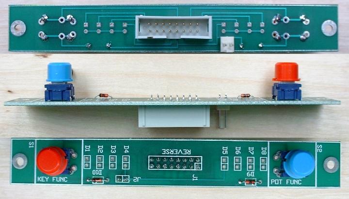
The Function Switch / LED Board
This board has 2 switches, used in pattern edit mode to select the function of the step keys, and upper knobs.
The first stage of assembly on this board is to fit the 2 NON-light emitting diodes, the switches, and the 16 way IDC and 2 pin SIP connectors.
N.B. Both connectors on this board are mounted on the REVERSE/SOLDER side of the board, as shown:
In order to fit the LEDs at the correct height, it is best to put them loosely in place, then solder them once you have adjusted them to the height you want above the panel.
N.B. THE LED ANODES GO IN THE HOLES WITH THE SQUARE PADS
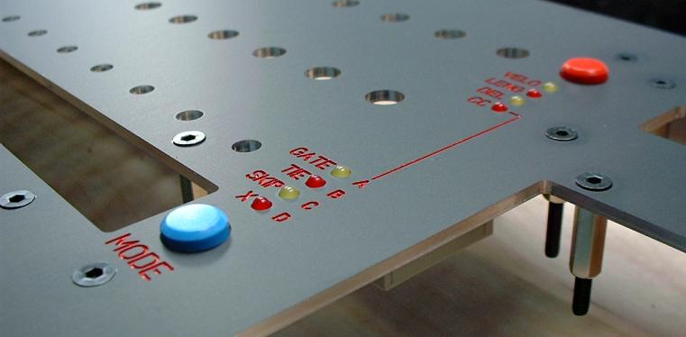
It's probably worth introducing the Schaeffer produced rack mount front panel I have designed here:
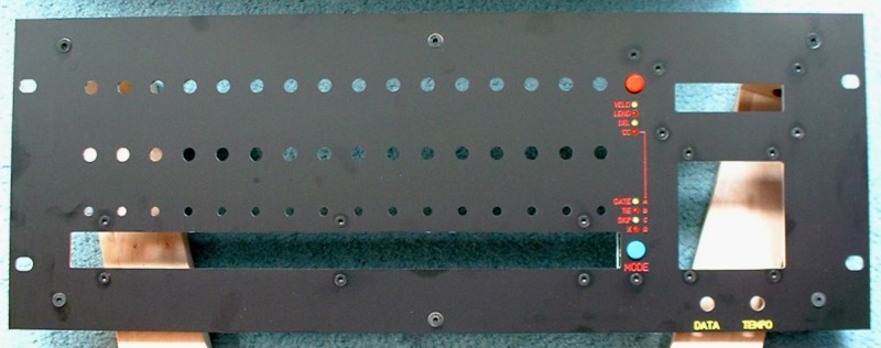
Note that greasy fingerprints seem to show up more on photos than they do in reality. These panels are a very nice quality.
I attach the function switch / LED board, step switch board, keypad board and LCD module to the front panel using countersunk 20mm M3 screws, with 14mm hex spacers for the step switch and keypad boards, and 10mm spacers for the LCD module and function switch board.
The screws / spacers I use look like this:
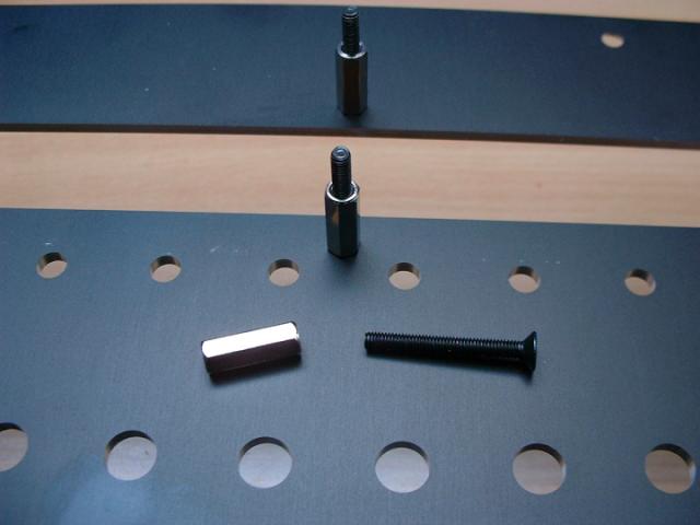
The screws are black, allen key headed types, that look very nice against the Schaeffer panel.
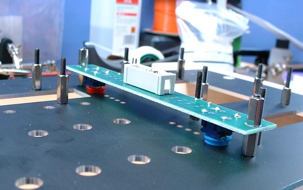
Once fitted the function board (still no LEDs) looks like this:
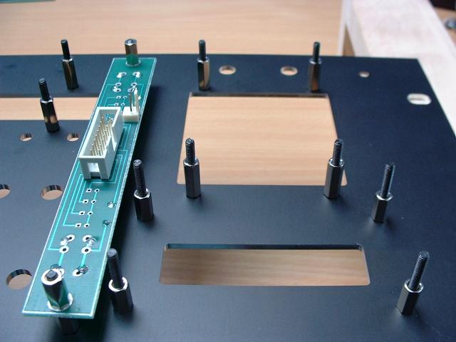
And from the side:
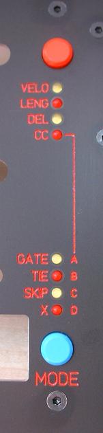
To fit the LEDs, I place them, the right way round, into their mounting holes, and then fit the board (facing upward) onto the panel. I then feed the LEDs through the panel holes so they are at an even height, and solder them in place:
Next Page... the Step Switch / LED board.

home