
And Building your P3 Sequencer continues...
Ribbon Cables etc.
Nearly all the interconnections inside the P3 are made with 16 way ribbon cable.
There are 2 main 'busses' - the pot board bus, and the switch/LED board bus.
The Pot Board Bus
The pot board bus has 3 connectors on it, which plug into each of the headers on the upper and lower pot boards, and the POTS connector on the main board.
Remember to use just enough cable to reach between the three headers - excess cable will increase the chance of noise being picked up.
Also remember to observe the correct polarity of the cable - pin 1 must go to pin 1 on ALL the connectors, or something might smoke.
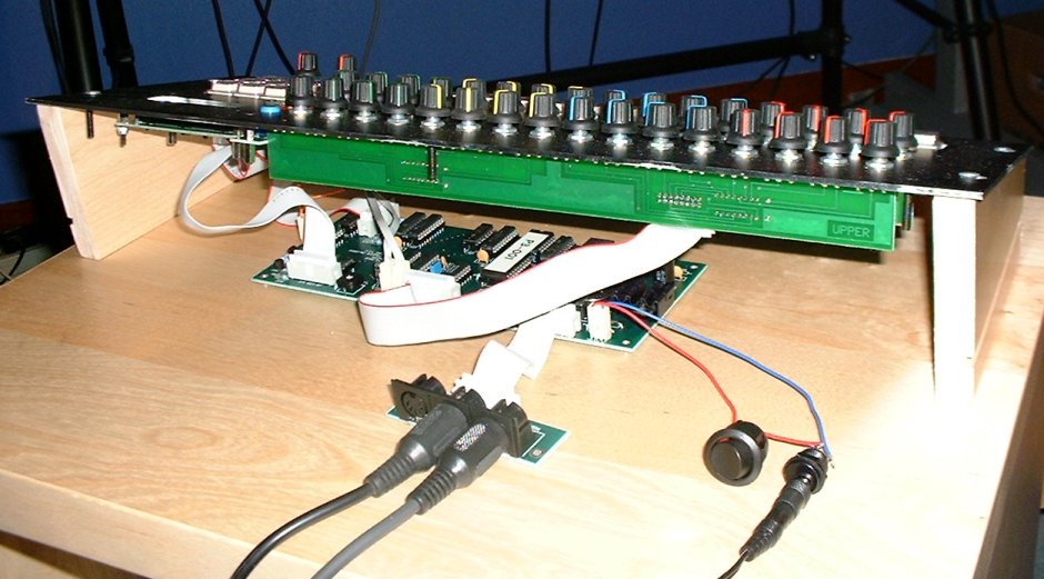
This photo shows the pot board wiring on my unit:
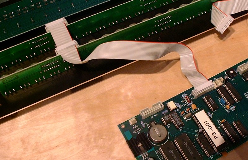
Note that the pot boards are mounted on the panel with the PCB 'above' the pots.
The Switch / LED Bus
The second bus is the switch/LED bus. This connects to all three switch/LED boards - the step switch board, function key board and keypad, and to the LED/SW connector on the main board.
There is also a single wire connection, from pin 1 of the AUX connector on the main board, to pin 1 of the 2 pin connector J2 on the function key board.
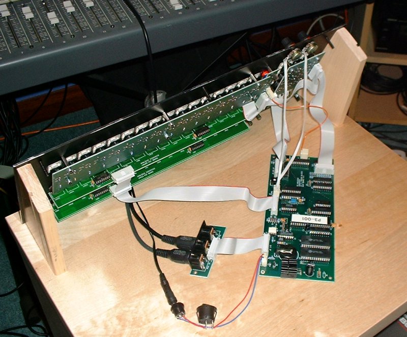
This photo shows these connections:
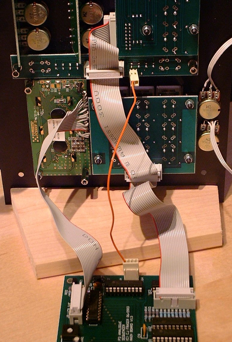
TOP TIP: If you have already fitted the lower pot board to the panel before you fit the Switch/LED board, make sure to plug the cable into the step switch / LED board before you fit it to your panel. Otherwise, you can't get it in, due to the proximity of the lower pots.
You can also see the connection from the LCD module to the LCD I/F connector on the main board. The preset VR1 adjusts the LCD display contrast.
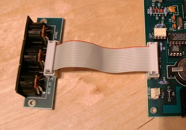
The DIN I/O Ribbon
The final ribbon cable connection is to the DIN I/O board. Not very complicated:
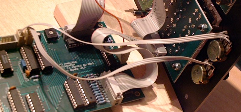
Pot Wiring
The Tempo and Data pots are also wired separately, each to their own 3 pin header on the main board. These are labelled TEMPO and DATA, oddly enough.
Pin 1 and 3 of the headers are +5 volts and 0 volts respectively, and should go to the outside pins of the pot, so that the wiper connects to the 5 volt end when it is turned fully clock-wise. Pin 2 of the headers connect to the wipers - the middle pins of the pots. I always connect them up the wrong way round to begin with.
Power Input
The final bit of internal wiring is the cable from the power input socket to the main board power input, with one wire going via the power switch.
An AC or DC supply of between 8 and 12 volts can be used. It should be able to provide at least 400mA (double the typical consumption of 200mA).
In the case of a DC input, pin 1 (with the square on the silkscreen) of 'J1 9VAC' on the main board should be connected to the negative / ground end of the supply. The rectifying diode, D6, will prevent any damage if DC of the wrong polarity is applied, but it won't power up.
My power input wiring looks like this:
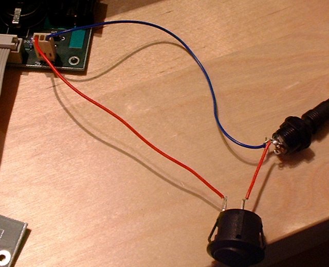
Remember not to wire up the switch and the socket before you put them through holes in a panel. I just have it wired up like this for testing.
The Final Assembly
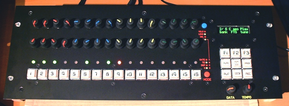
This is the current state of my own rack-mount unit. I still have the desktop case from the proto-type, but it doesn't yet have mounting holes for the function switches and LEDs.
I've not yet made a rear enclosure for the rack panel - I'm going to get this done shortly.
The rack panel shown above is currently screwed to two wooden end cheeks, made from some spare maple skirting board we had left after replacing the skirting in our house, as shown:
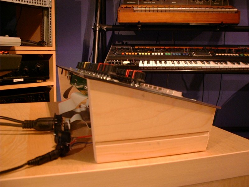
My plan is to have a sheet metal rear enclosure made that may or may not feature the wooden end cheeks. Wooden cheeks would be very nice with a desktop case using a Schaeffer front panel.
The easiest option for the rack mount unit would probably be to use the wooden cheeks, then fold up a three sided sheet of aluminium that could be screwed to the outside three edges of the wood, with holes cut in it for the DIN I/O jacks, power switch and socket.

home