
And Building your P3 Sequencer continues...
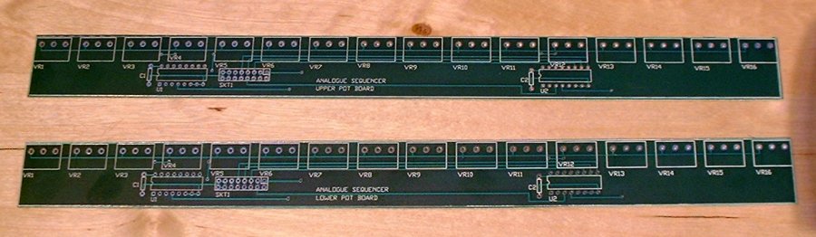
The Upper and Lower Pot Boards
These two boards are identical, except for the pins on the connector that carry the multiplexed voltages from the pots to the main board. The multiplexers are the ubiquitous 4051, two on each board.
Aside from those, each board has 16 pots, 2 capacitors for de-coupling, and a right angled IDC 16 pin connector.
Here are the bare boards:
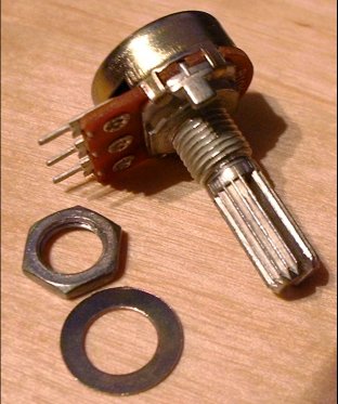
The pots I use come with an annoying little locating lug, that I cut off with an old pair of sidecutters:
With so few different components, assembly of the pot boards should be dead easy - apart from getting the pots to stay in the right place while you solder them.
The pots should be soldered in last, after the ICs/sockets, caps and connector.
I'd suggest loosely mounting them in your panel to hold them in line while you solder.
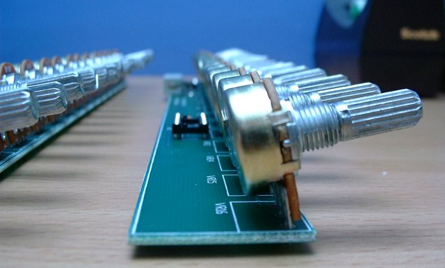
I hold the board facing down, and fit the pots in from below, working along the board so that eventually it's balanced on top of the pots like this:
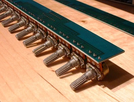
Note that I haven't soldered anything yet in this photo - the weight of the pots holds it in position.
Then I solder each centre pin, and check for straightness, and that the pots are flush to the board, before soldering the rest of the pins.
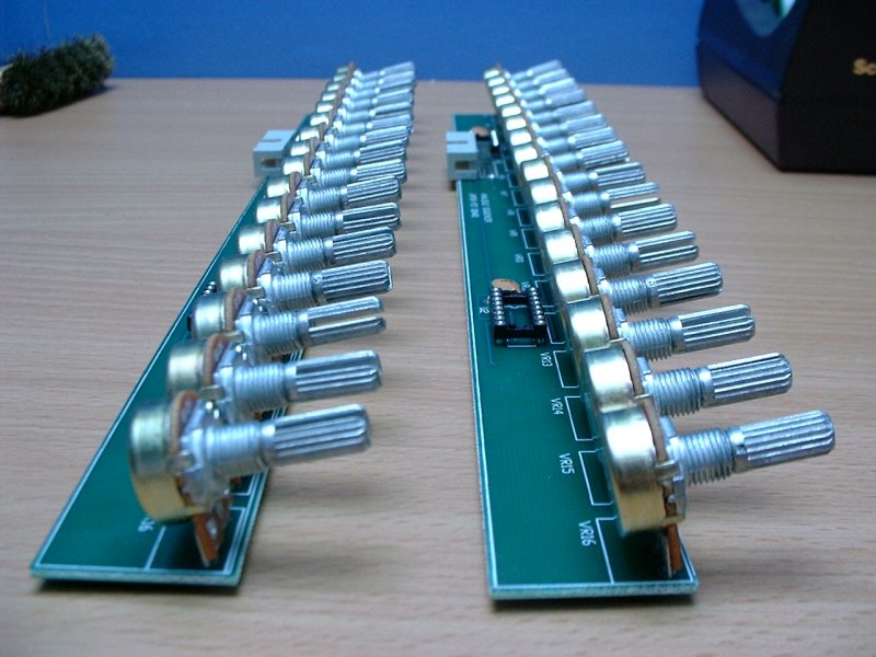
Once finished, the boards will look like this. Note that the pots are angled back slightly - this is so that the front end of the PCB clears the front panel when they are bolted on, and doesn't put any pressure on the pot pins.
Next Page... wiring the LCD Module.

home