PLED connector board
In order to simplify wiring of the display module, a small board is supplied that allows a 16 pin right-angled IDC connector to be fitted to the PLED module via a 16 pin PCB to PCB header:
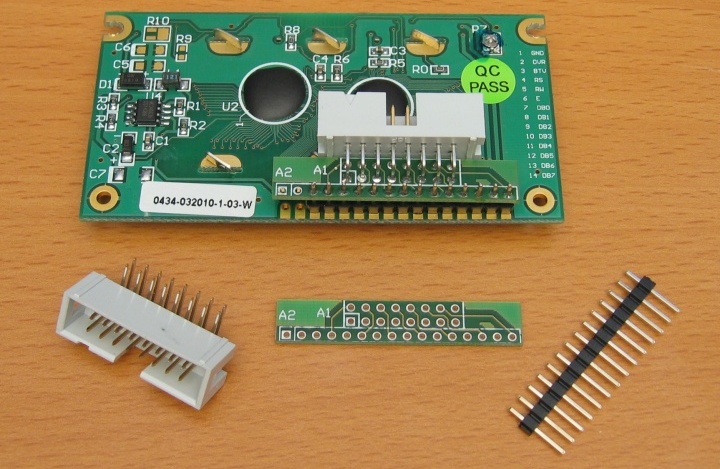
Note that only 14 pins of header are really needed, since the PLED modules do not use pins 15 and 16. Pins 15 and 16 are for the backlight power on an LCD module, so are required if you use an LCD.
Fit the IDC connector to the small board first, then trim the pins so that they wont touch the module PCB.
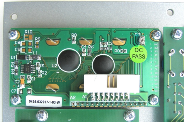
Next fit the PCB header to the module board, making sure the pins don't stick out the front far enough to short on the front panel.
Finally, fit the adaptor board to the header, making sure there are no shorts, and solder in place.
The PLED module mounting holes are 2.5mm diameter, so need to be carefully increased to 3mm with a drill in order to fit the M3 mounting posts on the P3 front panel:
back