Input/Output board
The I/O board features six 5-pin DIN sockets: one for MIDI in, four parallel MIDI outs (which all carry the same signal), and a SYNC socket.
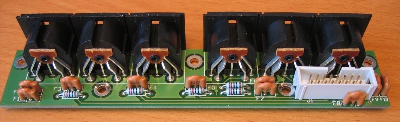
The complete board will look like this:
From hardware revision 1.6 on, the SYNC output socket on P3 carries both clock-only MIDI output, and DIN Sync 24 at the same time.
Both MIDI and DIN Sync use pin 2 for ground, but MIDI uses pins 4 and 5, while DIN Sync uses pins 1 and 3.
Testing of a number of devices has shown having both signals on the socket will not cause problems in most cases.
In the event that a conflict does occur, this can be resolved either by using a sync or MIDI cable with some pins disconnected, by disconnecting the pins internally, or by disabling the SYNC or MIDI output using a software option.
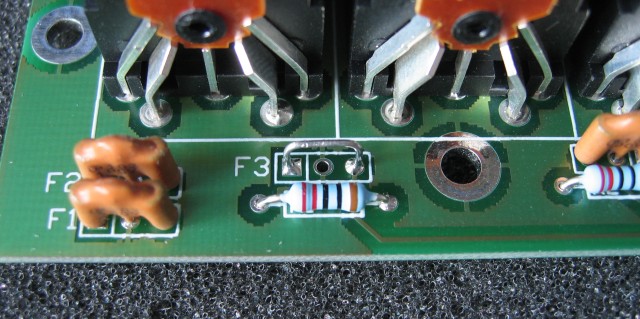
Production units are fitted with 3-pin RFI filters on all input and output lines, in order to safely exceed EU and FCC emission standards.
These filters are not strictly required if you are building P3 from a kit and not for commercial sale.
If you don't want to use them, wire links can be used in their place - the links should connect the outer two pads in each filter location, taking care not to short out against the centre connection, which is chassis ground:
back